4L60E Transmission Rebuild Tips
These are some general 4L60E transmission rebuild tips and tech info that you can use during your build.
Bellhousing bolts.
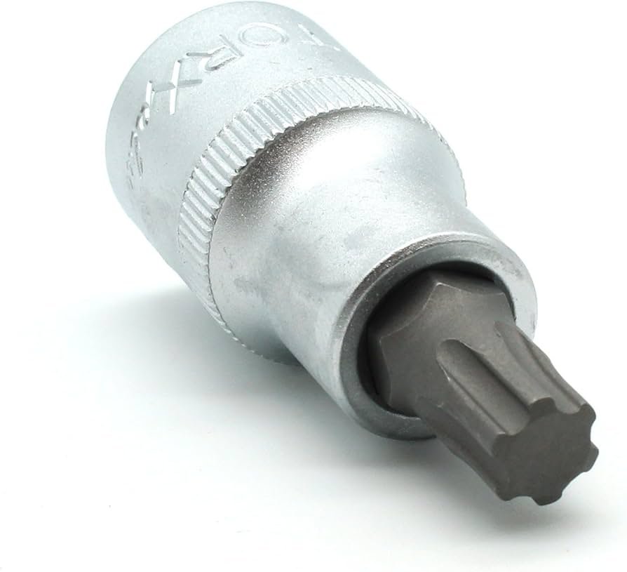
Most 4L60E transmissions will have torx head bolts holding the bellhousing against the case. You will need a Torx Plus 50 bit to remove them. A regular Torx 50 bit will not work properly.
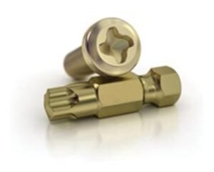
Later model 4L60E transmissions (2009 and up) will have Mortorq head bolts holding the bellhousing against the case. The picture on the is for illustrative purposes only. You will need a Mortorq MTS 4 socket.
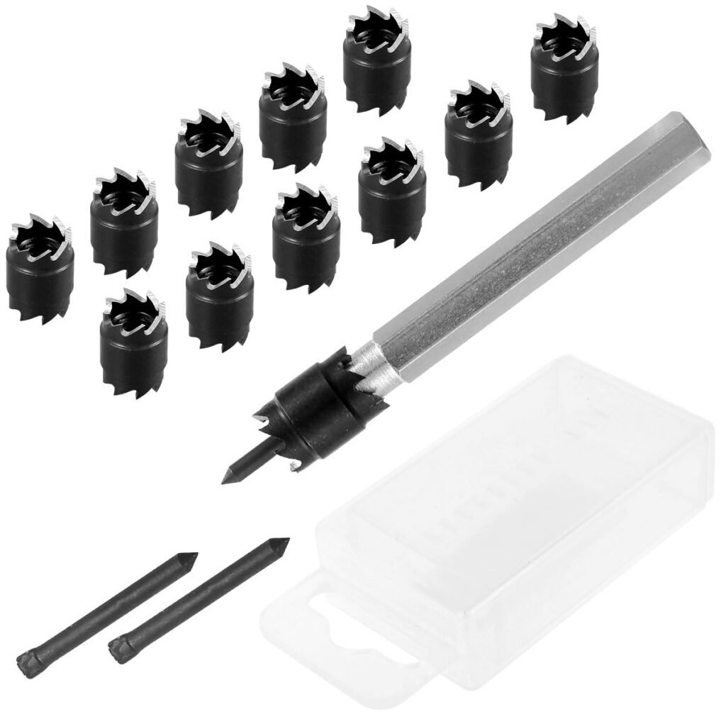
Stripped bolts – If you use the wrong bit or even when using the correct one, there is a real possibility the head bolt will strip. To prevent this, you can heat up the bellhousing if they don’t come out with an impact right away. You can use a portable torch and heat up the bellhousing where the bolts thread into.
If the bolts strip, you can use a bolt extraction kit, drill out the head with a 3/8 bit, a 3/8 rivet removal tool of your choice, or 3/8 spot weld cutter to drill out the bolt head.
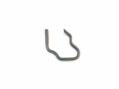
Snap Ring Pliers and tips
You will need a set of snap ring pliers mainly for the snap rings holding the output shaft, spring cages, TCC and Boost valves in the pump.
TIP: You can also use these to compress the anti clunk spring if you are unable to remove the center support during disassembly.
Snap Ring Removal tips
Safety First: Always use protective eye gear when removing snap rings. Here are some tips if you are having trouble removing one of the snap rings.
Output shaft snap ring: Set the transmission on its side. If you cannot get it out with the pliers alone, open up the snap ring using the pliers and while holding it open, use a 90 degree pick to grab the snap ring and pull it out to get it out of the groove.
Low reverse piston ring: If you cannot get it out with the pliers alone, open up the snap ring using the pliers and while holding it open, stick a long straight pick to keep it out of the groove. With the straight pick still in place, use a 90 degree pick to grab the snap ring and pull it out to get it out of the groove.
TCC and Boost valve snap rings: If you cannot get it out with the pliers alone, stick a straight pick into one hole of the snap ring to hold it in place. Use another pick (can be a 90 degree pick) to stick in the other hole of the snap ring and pull on it in the direction of the straight pick, and pull it out.
4L60E Transmission Rebuild Tips – Disassembly
Stuck anti clunk spring – Once you have remove the snap ring, if you cannot dislodge the center support by pushing on the output shaft, you may need to compress the anti cluck spring using a set of snap ring pliers, and hold it like that while you hit the output shaft with a rubber mallet.
Stuck input drum – sometimes the input drum gets stuck and cannot be removed just by pulling it out. This usually happens when the 3-4 clutch pack burns up and the transmission is still driven like that for a while. The high temperature from all the friction material being gone, causes the steels to weld together and sometimes weld to the input hub. If this happens, try removing the band and the reverse input drum (using a 90 degree pick). Then use a couple of bolts to put the bellhousing back on. Use some carboard on the floor, flip the transmission so it is sitting on the bellhousing. Lift it up 2-3 inches and let it drop. You might have to do this a few times to get the input drum to dislodge.
Watch this video explaining the process to free up a stuck input drum.
4L60E Pump related tools
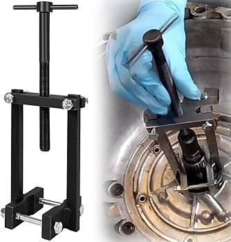
Pump removal
Clad seal case pumps are usually easier to remove than O ring seal pump cases. You can usually use a long screwdriver or pry bar to separate the pump from the case. Stick the screwdriver/pry bar in under the area where the filter goes into the pump, but make sure to slide it further in before attempting to pry the pump out. Don’t do it on the edge of the pump or you can break the small piece off. You can also insert your tool of choice in the area where the gear selector goes to pry it off. If that does not work, the you can use a tool like the one in the picture.
Pump Clearance
Always check pump clearance using a strait edge and feeler gauge. This is especially needed if the pump rotor or slide broke. If you replace the rotor and slide, but the clearance is out of specifications, then you run the risk of it breaking again due to excessive clearance.
Watch the video below to see how to check clearance
Pump alignment – reassembly
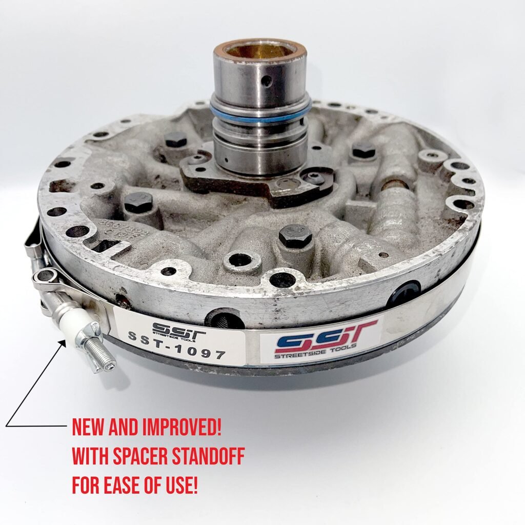
Use a tool like the one in the picture to align the two halves of the pump when reassembling to make sure everything aligns properly.
Pump Final Assembly Checks
After assembling the rotor inside the pocket with all the vanes and rings, add a few drops of fluid and make sure it spins freely by spinning it by hand about 10-15 times. Then once you have bolted both parts of the pump together, set it on the torque converter hub, make sure the rotor engages the tabs on the torque converter hub and spin it 5-10 times in both directions to make sure it spins freely.
Watch the video below to see how to check that the rotor spins freely
Pump to Case Seal
There are two types of pump to case seals, Wedge seal and O ring seal. Make sure the pump face you use matches the type of case you have. If you have a wedge seal type case (with a step) then use a pump assembly with a wedge style pump face; and vice versa for O ring type seal. Since the 4L60E pump is made up of two halves, you just need to make sure you use the correct style face. This means you can use the pump cover from an O ring type transmission along with the pump face from a Wedge seal pump and use it with a wedge seal type case.
Wedge seal type cases have a step where the pump goes
O Ring seal type cases DO NOT have a step where the pump goes
4L60E Transmission Rebuild Tips – Valve Body
4L60E Separator plate
If the paper gaskets are baked to the separator plate, you can put them on a pan filled with water, raise the temperature so it starts to boil, leave them for a few min, and then the stuck gaskets should come off a lot easier.
Watch the video below for a demonstration
If the hole for the 3rd gear checkball has been enlargened to where the checkball is stuck or goes through on the separator plate, you can use the fitzall repair kit. If the hole is enlarged, but the checkball does not go through, you might be able to close it back up by hammering the checkball hole. If the separator plate does not need repair (or was repaired with a hammer) you can replace the steel checkball with a Torlon checkball to prevent it from happening again.
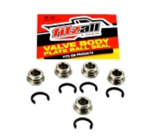
Watch the video showing the repair process using the Fitzall kit.
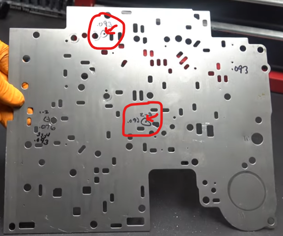
Separator plate modifications – Even if you are not going with a shift kit. It would be beneficial to drill out these two holes (circled in red) for better apply and release of 3rd gear. Click on the dropdown to see a picture from one of Nick’s Transmissions videos:
When reassembling the valve body, an inexpensive way of blocking the PWM valve is to use two 0.25″ checkballs. Watch the video below.
Watch the video of how to block the valve at the 8:30 min mark.
Shift Solenoids – Check resistance on the shift solenoids. It should be somewhere between 19-24 Ohms.
Watch this video showing how to test the solenoids. You can use a battery if you don’t have a charger.
Forward Accumulator Piston – Replace the forward accumulator plastic piston with an aluminum piston as well as the plastic 1-2 accumulator piston with an aluminum one.
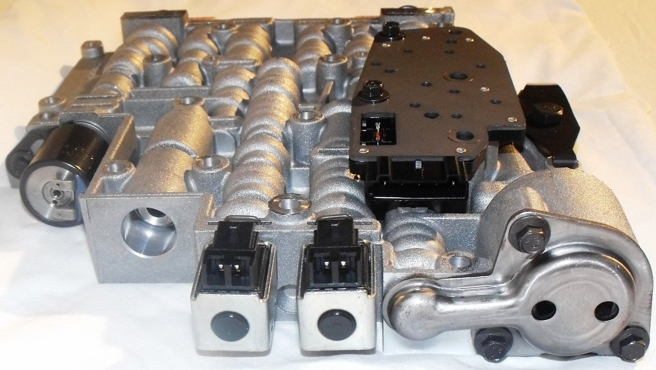
4L60E Valve body
If lockup was working fine, then most likely, you will not need to replace the TCC valve. If you want to replace it, you can use Sonnax TCC apply valve kit for your application. Replace the boost valve with a stock one or a Transgo 0.500″ oversized valve to increase the line pressure.
4L60E Reverse input drum
Check with lamp for straightness. Place a straight edge across the surface and shine a lamp from the other end. If you see light coming through then replace the drum. If it checks out, you can use a red scotch brite pad to clean the surface.
Watch the video below at the 4 min mark to learn how to check the drum.
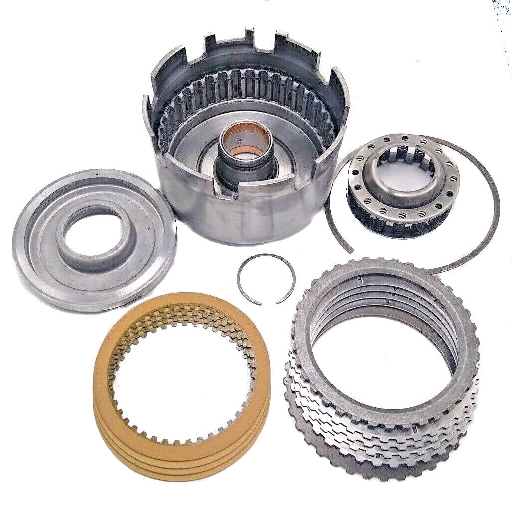
4L60E Transmission Rebuild Tips – Input drum
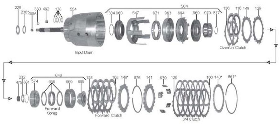
This can be one of the main sources of failure for the 4L60E transmission. The drum sometimes leaks from the area where the input shaft is pressed into the drum. It is a good idea to do a “wet pressure test” where you assemble the drum, then flip it over, add fluid to that area and apply compressed air to the 3-4 feed hole and check for bubbles. Even if it passes that test, it can still leak when the fluid/drum reach operating temperature of 160F, which can cause the aluminum drum to expand causing a leak. If you rebuild the transmission for a 3-4 burnup and it still slips after the rebuild even though all other sources of 3-4 burn up have been addressed, then the drum most likely develops a leak at operating temperature. The only option there is to replace the drum.
Watch the video of an input drum that FAILED the pressure test.
If the drum fails the pressure test you can try to “repair” it. Even if you want to be safe and try to prevent the leak from developing in the future you can follow the process explained in the video. Some builders do this to all their transmissions, others advise against pressing the shaft out if it is not leaking. It will be up to you if you want to try it or not if you don’t have a leak. The method involves pressing the shaft out of the drum (you will need access to a press), and add retaining compound, Loctite, or JBWeld to the shaft and press back in.
Watch the video showing the repair process.
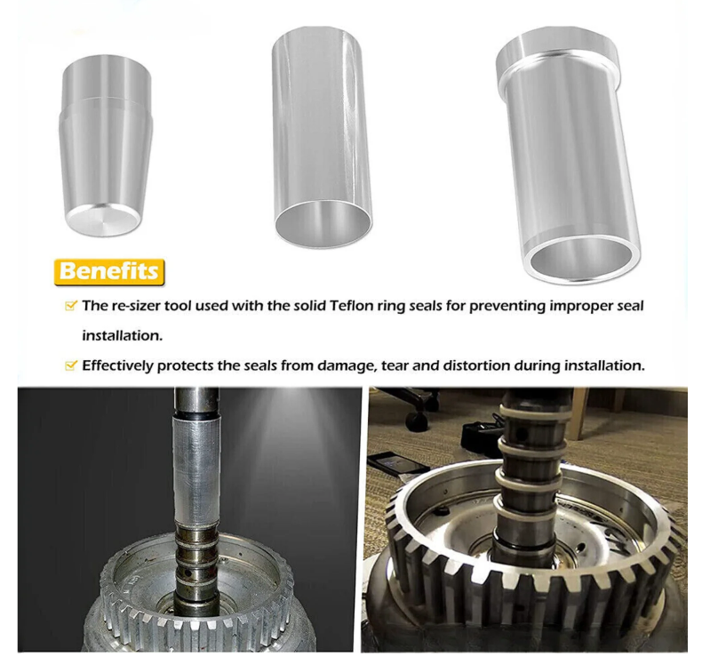
Make sure to always replace the input shaft and pump stator sealing rings. The tool is not that expensive, and you ensure to get good functioning sealing rings to avoid cross leaks.
4L60E Transmission Rebuild Tips – case final assembly
Before final installation of the input drum and reverse input drum into the case, you can do an air check along with the pump. Simply install the reverse input drum on top of the input drum, then install the pump onto the reverse input drum, flip the entire assembly and add compressed air through the pump feed holes.
Watch the video showing the air check. The user does not have the input sprag installed, but you will most likely have it installed as you are getting ready to install the input drum into the case. That does not make a difference, you just won’t be able to see the frictions move as well, but you will see movement.
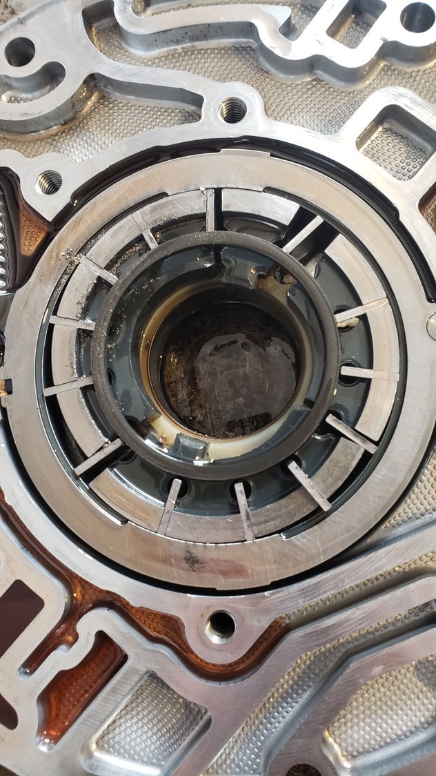
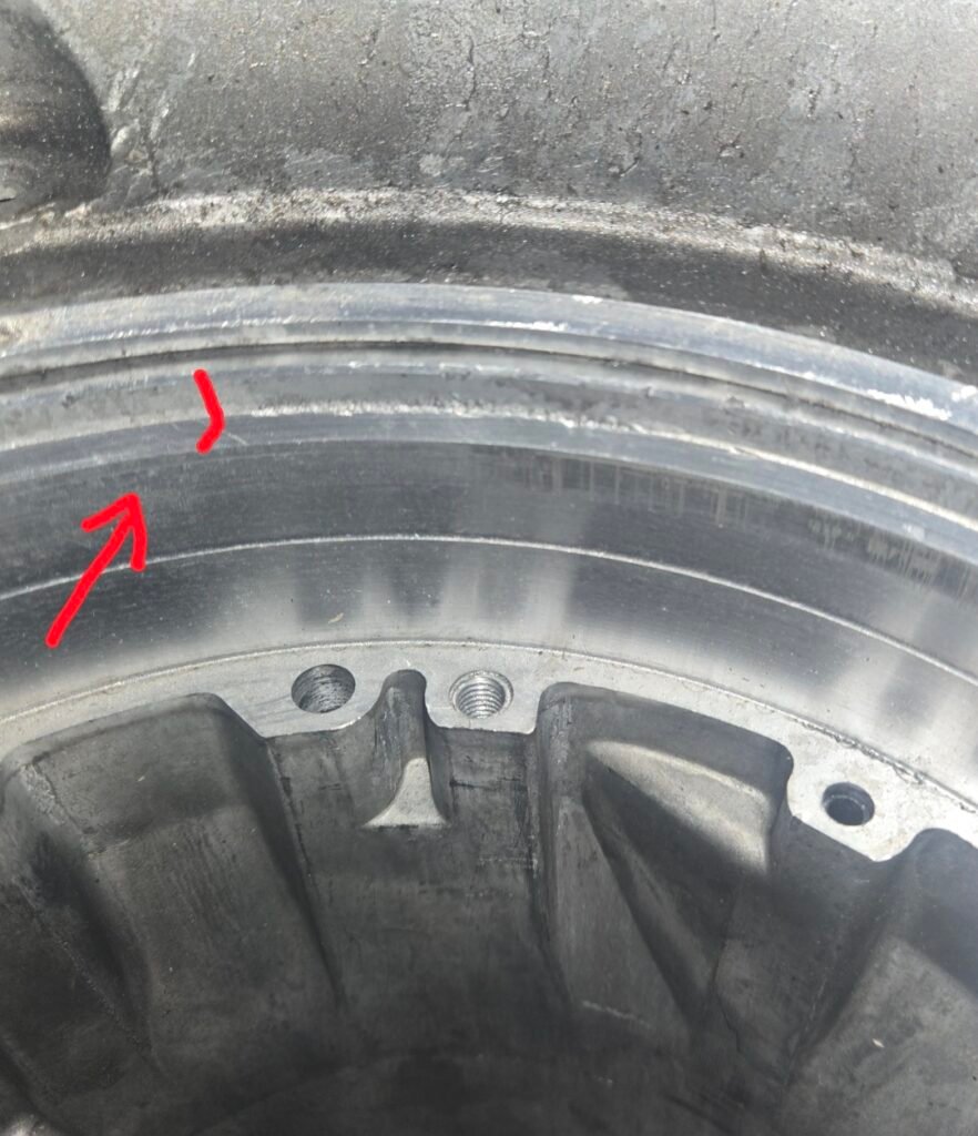
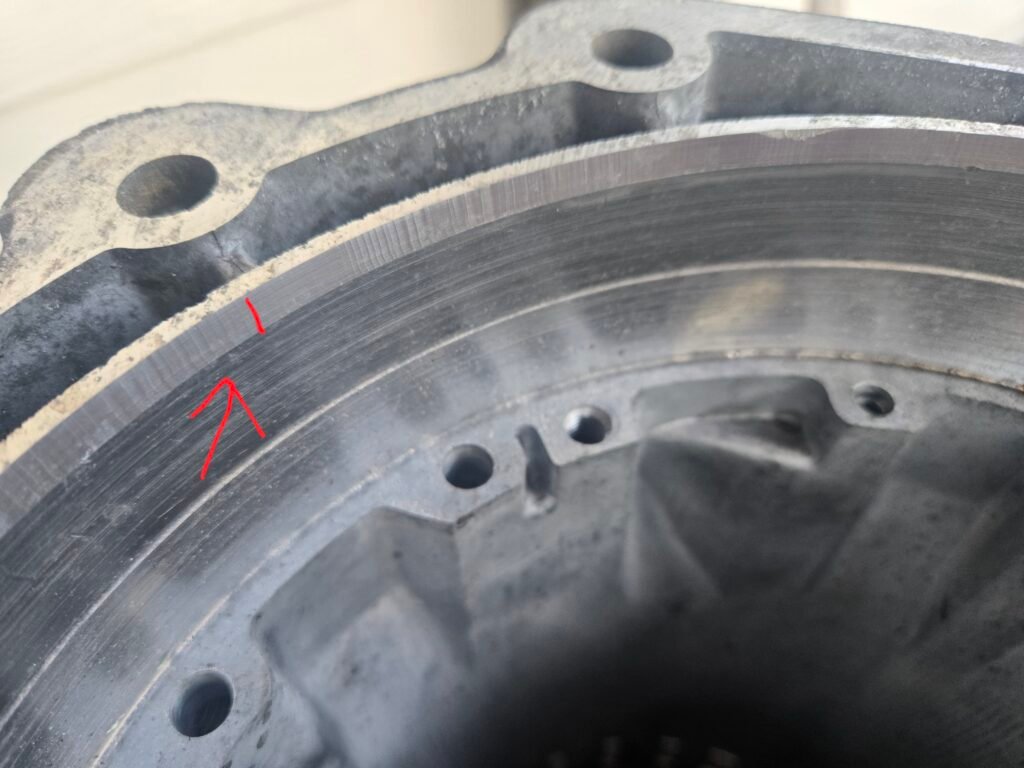
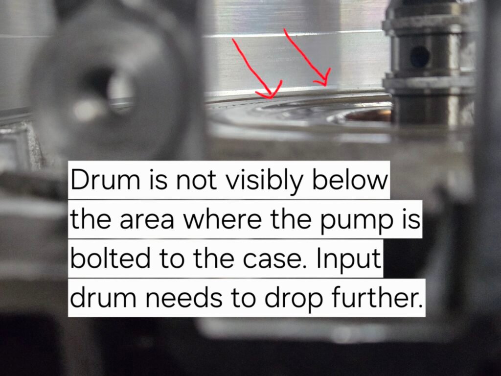
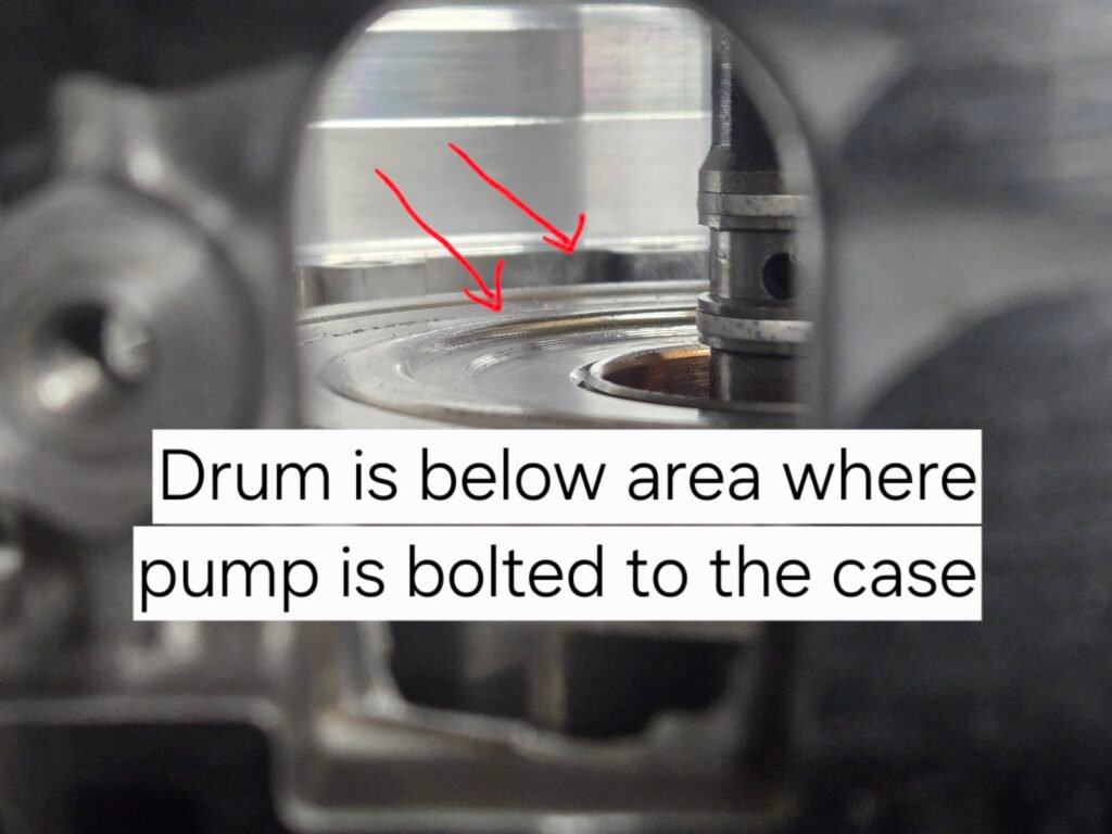
Ensure the input drum and reverse input drum assembly is seated all the way by looking through the area where the filter goes into the pump (obviously the pump will not be there at this point). You should be able to see the reverse input drum sitting below the area where the pump bolts to the case.
See the pictures for a visual explanation.
First picture shows no difference between the reverse input drum and the case area where the pump is bolted in.
Second picture shows a noticeable difference between the reverse input drum and the case area where the pump is bolted in.
Before final installation of the pump into the case you can do an air check to make sure the band is applying and the servo working as expected. You can accomplish this by applying compressed air to servo feed holes and checking the band for movement. You need to have the input and reverse input drums, the band, and servo installed.
Watch this demo on how to check the servo before installing the pump.
Once the pump has been installed and torqued down, you can use a test plate to make sure all the clutch packs and band are applying as expected by using a test plate. This helps ensure that none of the sealing rings on the input shaft or pump stator got damaged when installing the pump.
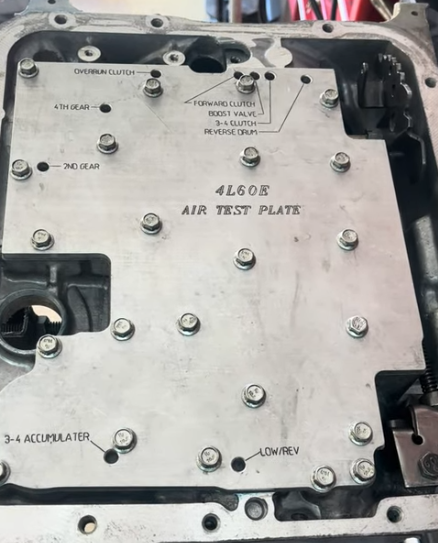
Watch this video showing what a successful test sounds like.
4L60E Transmission Rebuild Tips – Final Assembly
There are two types of oil pans and filters (deep or shallow pan). Make sure you buy the correct one for your application. The easy way to tell is by looking at the bottom of your oil pan. If it is flat, then you have a shallow oil pan. If there is a step towards the rear of the transmission, they you have a deep oil pan.
If you are replacing your vehicle speed sensor (VSS), make sure to only buy AC Delco or OEM sensors. Some of the aftermarket sensors fit, but don’t work well. If the transmission does not shift, check the speedometer. If it does not move, then that is why it won’t shift. There is no signal to the ECU telling it what speed you are driving at, and therefore it will not command the transmission to shift.
Make sure the torque converter is fully seated in the pump before installing the transmission. It is not about the number of bumps you feel when installing it. It is about making sure the tabs on the torque converter engage the rotor inside the pump. The best way to tell is by taking a straight edge, piece of wood or pipe across the bellhousing once the torque converter is installed. You should have about a 1/4″ – 1/2″ gap between the straight edge and the tip of the torque converter (pilot) in the center. You should have about a 1 – 1 1/4 inch gap if you line up the torque converter bolt hole with the straight edge. Not seating the torque converter correctly will most likely damage your rotor causing the transmission not to move at all.
Watch this video explaining how to check the torque converter is installed correctly.
Rebuild Now
Discover expert tips and guides to rebuild your 4L60E transmission.