The electrical case connector is the first thing to check when swapping or rebuilding a 4L60E. GM changed the connector four times over the transmission’s production run, and grabbing the wrong one means the harness won’t plug in — or worse, it plugs in but the pinout doesn’t match. This guide covers every 4L60E case connector version with photos, year ranges, interchange notes, and pinout charts so you can identify yours in seconds.
Quick Identification Chart
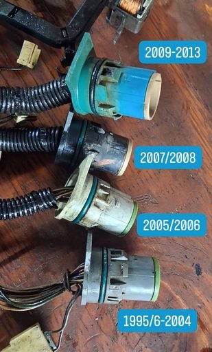
| Pins | Years | Shell color | Key change |
|---|---|---|---|
| 12 | 1993–1994 | White/cream | Original design |
| 13 | 1996–2004 | Green | Also used on 1995 standalone applications |
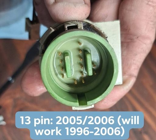
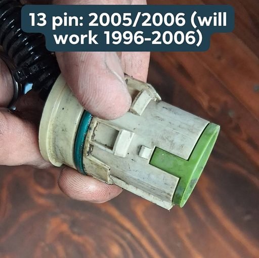
| 13 | 2005–2006 | Green/tan | Revised shell, same 13-pin layout |
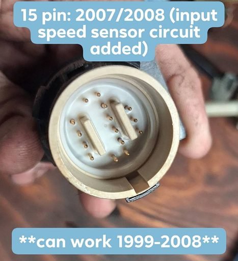
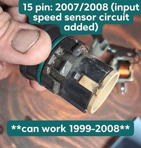
| 15 | 2007–2008 | Black | Input speed sensor circuit added |
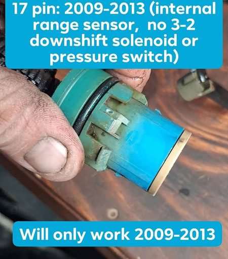
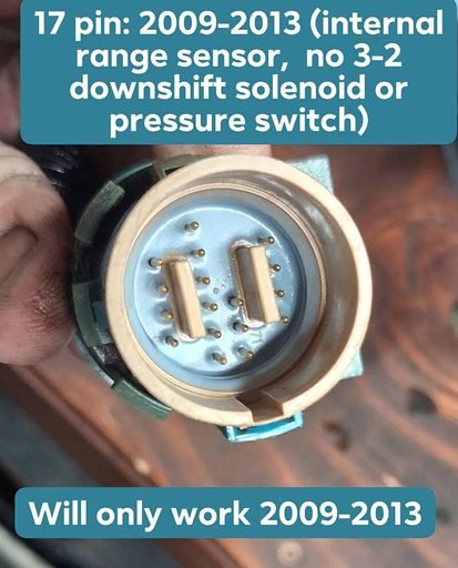
| 17 | 2009–2013 | Teal | Internal range sensor; 3-2 solenoid and pressure switches deleted |
12-Pin Connector (1993–1994 Only)
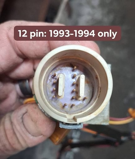
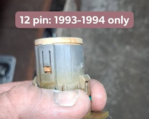
The original 4L60E case connector. White/cream shell, 12 pins, and it only fits 1993–1994 — nothing else interchanges with it. If your connector looks like this, you’re working with the earliest version of the transmission.
13-Pin Connector (1996–2004)
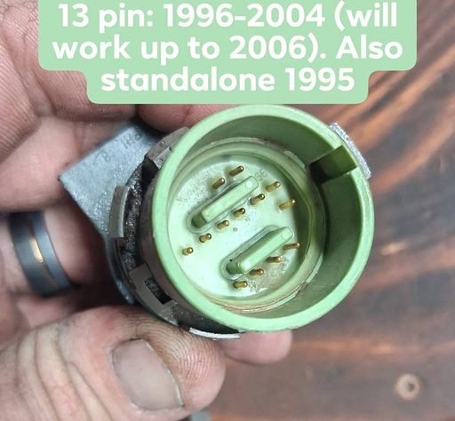
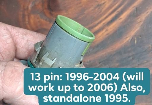
The green 13-pin connector is the most common version you’ll run into. It was also used on 1995 standalone applications, and it will work in vehicles up through 2006.
13-Pin Connector (2005–2006)
GM revised the shell for 2005–2006 (green/tan coloring) but kept the same 13-pin layout. Backward compatible across 1996–2006 applications.
15-Pin Connector (2007–2008)
Black shell. The big change for 2007–2008 is the added input speed sensor (ISS) circuit — two extra pins over the 13-pin versions. A 15-pin case can work in 1999–2008 applications.
17-Pin Connector (2009–2013)
Teal shell and the biggest redesign of the bunch: an internal mode (range) sensor replaces the external pressure switch manifold, and the 3-2 downshift solenoid is gone. This one is 2009–2013 ONLY — it does not interchange with any earlier year.
All Four Generations Side by Side
Interchange Notes: What Swaps With What
- 12-pin (1993–1994): no interchange — 1993–1994 only.
- 13-pin (1996–2004): works up through 2006; also fits 1995 standalone applications.
- 13-pin (2005–2006): works across 1996–2006.
- 15-pin (2007–2008): can work in 1999–2008 applications (the input speed sensor circuit goes unused on earlier vehicles).
- 17-pin (2009–2013): 2009–2013 only. The internal range sensor and deleted 3-2/pressure-switch circuits make it incompatible with earlier harnesses and controllers.
4L60E Case Connector Pinout (13-Pin, 1996–2006)
Pin views are looking into the case connector on the transmission side.
| Pin | Function |
|---|---|
| A | 1-2 shift solenoid (ground signal from PCM) |
| B | 2-3 shift solenoid (ground signal from PCM) |
| C | EPC solenoid high |
| D | EPC solenoid low |
| E | 12V ignition feed (solenoid power) |
| L | Transmission fluid temp (TFT) sensor signal |
| M | TFT sensor ground |
| N | Pressure switch manifold – Range A |
| P | Pressure switch manifold – Range C |
| R | Pressure switch manifold – Range B |
| S | 3-2 downshift solenoid |
| T | TCC solenoid |
| U | TCC PWM solenoid (1995-up) |
2007–2008 (15-Pin) Adds
The 15-pin connector adds the input speed sensor circuit to the layout above:
| Pin | Function |
|---|---|
| K | Input speed sensor (ISS) signal |
| V | Input speed sensor (ISS) low reference |
2009–2013 (17-Pin) Changes
The 17-pin connector keeps the core solenoid pins (A–E, L, M, T, U) and the ISS pins (K, V), adds the internal mode switch circuits, and deletes the 3-2 solenoid and external pressure-switch signals:
| Pin | Function |
|---|---|
| A | 1-2 shift solenoid (ground signal from PCM) |
| B | 2-3 shift solenoid (ground signal from PCM) |
| C | Pressure control solenoid high |
| D | Pressure control solenoid low |
| E | Ignition 12V feed (solenoid power) |
| F | Internal mode switch – range signal A |
| G | Internal mode switch – range signal B |
| H | Internal mode switch – range signal P |
| J | Internal mode switch – range signal C |
| K | Input speed sensor signal |
| L | TFT sensor signal (high) |
| M | TFT sensor ground (low) |
| N | Internal mode switch ground |
| T | TCC solenoid (ground signal from PCM) |
| U | TCC PWM solenoid (ground signal from PCM) |
| V | Input speed sensor low reference |
| W | Internal mode switch – park/neutral signal |
Solenoid Resistance Quick Check
You can test solenoids without opening the transmission by checking resistance at the case connector. Typical values (verify against a service manual for your year):
| Component | Typical resistance |
|---|---|
| Shift solenoids A / B | 20–40 Ω |
| TCC (on/off) solenoid | 20–40 Ω |
| TCC PWM solenoid | 10–15 Ω |
| EPC (force motor) solenoid | 3–8 Ω |
| 3-2 downshift solenoid (1996-up) | 20–30 Ω |
| Input speed sensor | ~900–1,400 Ω |
| TFT sensor | Varies with temperature (thermistor) |
4L60E Connector FAQ
How do I tell which 4L60E case connector I have?
Count the pins and check the shell color against the chart above — pin count plus color nails it to a year range every time.
Can I put a 2009+ 17-pin 4L60E in my older truck?
No. The 2009–2013 connector’s internal range sensor and deleted 3-2/pressure-switch circuits make it incompatible with earlier harnesses and PCMs.
Will a 2007–2008 15-pin transmission work in my 2004 truck?
The 15-pin case can work in 1999–2008 applications — on earlier vehicles the input speed sensor circuit simply goes unused.
Chasing an electrical shifting problem? Start with the 4L60E troubleshooting and diagnosis guide. For the full mechanical teardown, see the 4L60E rebuild resources.